First things first, disassembly time! In the picture below we can see the different components making up the hoverboard. We can see two gyro boards, one main board and the battery.
Each gyro board contains a Cortex-M3 processor calculating its orientation from an MPU-6050 accelerometer/gyro sensor and sending it over UART to the main board, which is responsible for driving the motors.

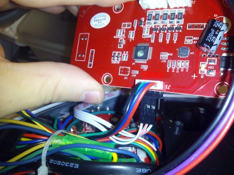
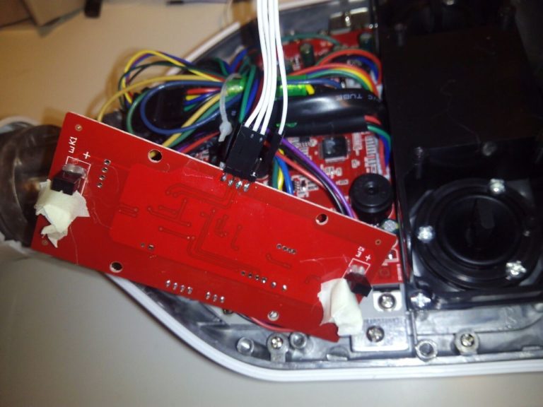
Thanks to Drew Dibble's work we know that the UART lines run at 26315baud, with 1 stop bit, no parity and LSB-first. In the pictures below we see the serial bus and the IR sensors used to check if the user is standing on the board, which we will spoof with a bit of tape.
By any chances have you dumped the firmware that goes on the STM32F mcu of the gyroscope boards ? I’ve accidentally erased mine while trying to read it 😛
Ouch! No, sorry, I just hooked it up to a logic analyzer to get the protocol, I didn’t think of making a copy of the firmware.
Have you tried extracting it from the other board and copying it to the one you wiped?
please help me i have 5 hoverboard that erased firmware
fuze.ece@icloud.com
can i use for power wheelchair ?
The code on the GitHub seems different from your explanation here
Should it be “motor1.format(9,SerialBase::None,1);” before you putc(256)?
Why format twice? Will it work in this way?
Here is the code on GitHub
motor1.putc(00);//Start byte
motor1.putc(sp[1]);
motor1.format(8,SerialBase::None,2); //Expects 9bit, 1stop, receives 8bit,2stop -> MSB=first stop bit=1
motor1.putc(sp[0]);
motor1.format(9);
motor1.putc(sp[1]);
motor1.putc(sp[0]);
if(motOn==1) motor1.putc(0x55);//End byte
Yeah… that’s one of those *brilliant* comments that you think is perfectly clear until you try to understand it a couple of years later 🙂
I think I wrote that as a hack because Mbed wouldn’t let me add a stop bit to the 9-bit port, so I instead added a second stop bit on the 8-bit port, effectively having 9+1 bits, where the MSB would always be ‘1’ (the first stop bit). That way to send the start byte ‘0x100’ I sent ‘0x00’ so that the sent value would be 1+00.
Anyway I remember spending a good amount of time reading the values on the logic analyzer and trying different things until I got it to work, and once it did I didn’t touch it.
You could of course try using “motor1.format(9,SerialBase::None,1);” it’s perfectly possible that it has been solved in the meantime 🙂
Hi,
Very cool project! Where did you buy that specific potentiometer? Can’t find something exactly like that.
Cheers,
Sophie
Thanks! Unfortunately I don’t have an MPN, it’s just a joystick I took from an old RC controller, but if you search for ps2 joystick modules for arduino you’ll find very similar ones.
Hi, cool project! Is there a github repo available?
Yours Johannes
Hi, thanks! The repo is that of my OpenChair project, here it is https://github.com/majinstudios/OpenChair/tree/master/Software/lib/OpenChair
Hi Alvaro, thank you for the answer. Thus it is necessary to put a new firmware on the mcu.
Not really, I just disconnected the accelerometer boards and connected a dev board instead to simulate the angles, so the hoverboard remains intact and can be reused as normal by plugging back in the original boards